


Getting Started
Programming your CNC Spindle Grippers to safely and consistently machine your parts can seem intimidating at first, but we're here to help. We've used Spindle Grippers for thousands and thousands of parts, and have never had a machine crash or a mis-loaded part, so they're super reliable when you know how to use them.
Before you get started, you'll need the following:
- A good text editing software with an NC or G-Code plug-in; we recommend Visual Code or Sublime Text 3
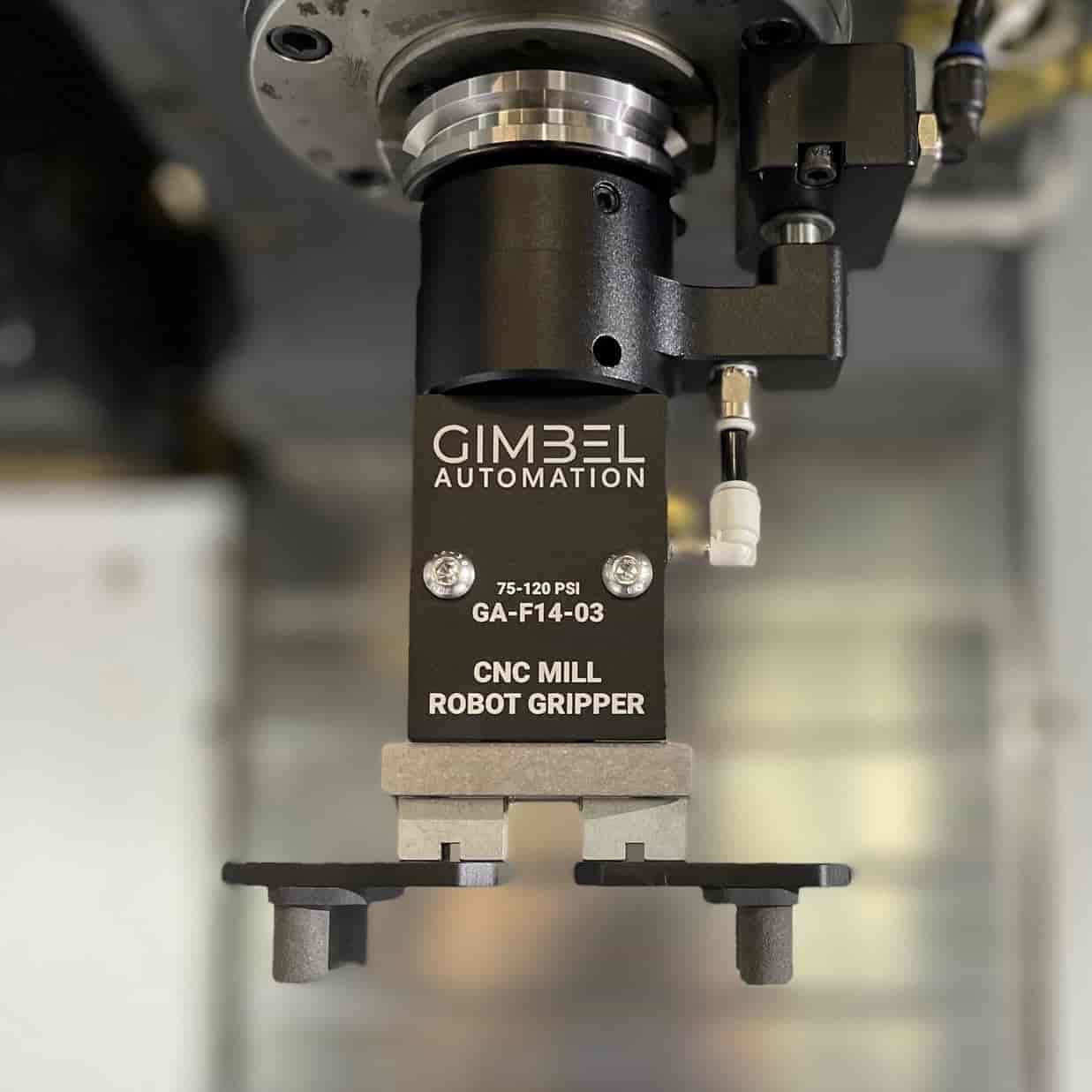
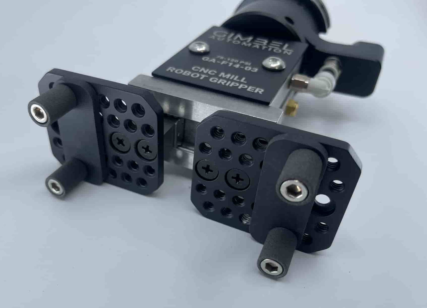
- A Gimbel Automation CNC Spindle Gripper that is set up on your machine
- An Automated Vise that is set up on your machine, ideally a Gimbel Automation Air Vise
- A method of clearing chips; we recommend a CNC Spindle Fan
Note that for this to seamlessly work, we highly recommend using the M-Codes to control two-way solenoids, and avoiding hydraulic vises or other solutions that don't offer consistent clamping repeatability.
An Example Code Editor Makes Editing Easy (Visual Code):

Work Coordinate Offsets
As machinists, Work Coordinate Offsets (WCS) are at the core of everything we do. The key to starting to easily implement Spindle Grippers is to stop thinking in absolute coordinates, and start thinking in relative ones. In order to approach gripper loading effectively, it's critical that we establish a offsets for the following:
- The part's machining location in the vise
- Each position in the tray's XY Location
- The tool length offset of the Gripper loaded with the material stock
We'll start with the easiest of the offsets: The Tool Length Offset of your gripper. Of course, your Gripper will have a piece of stock in it, so it's best to think of your Gripper's length offset as the total length of the Gripper loaded with the stock material before any machining has been carried out. We'll call this, Total Gripper Length from here on out.
Finding and setting your Total Gripper Length is easy: just call up the Tool Pocket that your gripper is loaded in, and insert a piece of your stock manually into the Gripper. Be sure that the stock is in full contact with your Gripper's rubber compression pads. In order to hold the stock in the gripper, we usually use an F-Clamp across the Gripper Plates to hold the stock in place during tool probing.
Now that you have your Gripper loaded with your stock, simply move it over to your Tool Setting Probe and run the Macro for a manual Tool Length. This should be the same (non-rotating) macro that you would use for picking up a single insert of a Shell Mill.
Now that we've found the Total Gripper Length, you can remove the clamp and remove the stock from your Gripper.
The next step is also easy: finding your machine position of your stock; we'll call this spot the Machining Position. In most first operations, you won't be using softjaws. The easiest way to do this is to insert your material into your Gimbel Automation Air Vise, and use the M-code required to clamp the part. Then, you can find the XY Center of the component and set it to your G54 X and Y coordinates.
Remember how we set the Total Gripper Length to the bottom of our stock material? Be careful here -- the Z coordinate of your Machining Position work offset needs to be the bottom of the material in its clamped position in the vise for this to work properly. When using hard jaws, we usually probe the stepped feature that the bottom of the material rests against.
The last position of concern is that of our gripper tray pockets. There is two approaches to this: The Tray First Pocket Approach and the Tray Center Pocket. For this tutorial, we're going to show you how to set WCS's for the Tray First Pocket approach.
So what does "First Pocket" mean exactly? The First Pocket is simply the bottom left pocket of your gripper tray. To set the Tray First Pocket Position, simply probe the XY Center and Z Bottom of the first pocket in your machined gripper tray. We usually set the Tray First Pocket Position as G55 by probing the XY center and bottom face of our Tray First Pocket and setting those as G55 X0 Y0 Z0.

Think of your Tray as a XY Matrix, with the following positions:

In the macro-driven code that comes later, you'll see these coordinates as line numbers that will reference M97 PXXX, where XXX is the line number.
So How Does this All Come Together?
The order of operations is pretty simple here:
- Using the Gripper, move to G55 X0 Y0 (Tray First Pocket Position), then lower to G55 Z0 and Clamp the Gripper
- Raise the Gripper up to clear fixtures (Usually to G53 Z0)
- Rapid XY to G54 X0 Y0, directly above the part position with the vise open
- Lower the Gripper with the loaded part to G54 Z0, then clamp the Vise
- Release the Gripper and Rapid to G53 Z0 for clearance
- Machine the part with your CAM-generated G-code
- Clear the machining area, usually with a spindle fan or air blade
- Repeat Steps 1-7 until you've machined all of your parts, except offset G55 coordinates for the linear pattern you used in machining your Part-Loading Tray
Using Macros
So how do we actually generate the code, now that we have all of our work offsets sorted?
The trick to doing this all relatively cleanly is to have Macros so the instruction code for your machine only has to be present once, even if it's used several times over the course of executing the full program. For this tutorial specifically, we'll focus on Haas machines, but other machines, such as Fanuc, should have very similar Macros and code structure.
There are two approaches for getting code to jump around and repeat: M97 and M98. M97 jumps to a part of your program by line number, and M98 will jump to an entirely different program. M98 is more flexible and powerful, but far easier to mess up and isn't self-contained. If you are new to Gripper programming, please become comfortable with M97 programs before ever touching M98.
In g-code M97 is followed by PXXX, where the "XXX" is the line number you'd like to jump to. For instance, M97 P100 will jump to line number N100, and continue until it hits an M99 that jumps the code back to the main program (jumps to the line after the M97 code).
Because of this, gripper programming involves using standardized line numbers, so you won't want to include any line numbers in the machining G-code you copy-paste into your Gripper template g-code.
Gripper Template G-Code Sections
Main Sections:
- Beginning G-Code
- Macro-Controlling Code
Macro-Driven Sections:
- Macro-Driven Repeating Sections:
- G54 Positions Code (for part loading)
- G55 Tray Positions Code (for part loading and depositing)
- Tray Retrieval and Vise Deposit Code (Get Stock)
- Machined Part Retrieval Code
- Machined Part Tray Deposit Code
- Chip Clearing Code
- Machining Code (what cuts the part)
I know this all looks like a lot right now, but I promise once you've made a single template and achieved this one time, it goes seamlessly every time after that. If you've purchased a Spindle Gripper from us, reach out to us and we likely have a template for your type of machine ready to go for an easy out-of-the-box coding experience.
Example Code Sections
Beginning G-Code:
The beginning code is just the same code you'd see at the start of any g-code for your machine. This is an example that we use on our Haas VF-2YT with a gripper system.
Macro-Referencing Code
This is the code that's doing the bulk of the work, controlling your Gripper and machining code.
Here is an example of Macro-Referencing code section for a single row of five parts:
G55 Tray Position Code
This section contains the positions as Macros for the five parts in the tray we want to machine.
Tray Retrieval and Vise Deposit Code
This is the section that grabs parts from the G54 Vise location, and picks them to be placed into the gripper tray.
Machined Part Retrieval Code
This code lowers the gripper, grabs the part, raises the gripper, goes to the G54 X0 Y0 , opens the vise, lowers to G54 Z0, close the vise, opens the gripper, and raises the gripper out of the way for machining.
.
Machined Part Tray Deposit Code
This code goes to G54 X0 Y0, opens the gripper, picks up the part by moving the gripper to G54 Z0 and clamping the gripper, and then unclamps the gripper and put the part back in its respective location.
Machined Part Tray Deposit Code (Significant Material Removal)
Note that in some cases, you will remove a significant amount of material in a facing operation or similar, and in these cases, you'll want to lower the gripper by the amount faced off of the part.
So, if we removed 0.125" in a facing operation, we would replace this line in the code from the previous section (Machined Part Tray Deposit Code):
G1 Z0. F20.; (Move to Z0 in G54)
G1 Z-0.125 F20.; (Move to Z0 in G54)
Chip Clearing Code
Machining Code